cam ?'s

Yamaha Raptor 350 & Warrior Forum

Help Support Yamaha Raptor 350 & Warrior Forum:

This site may earn a commission from merchant affiliate links, including eBay, Amazon, and others.
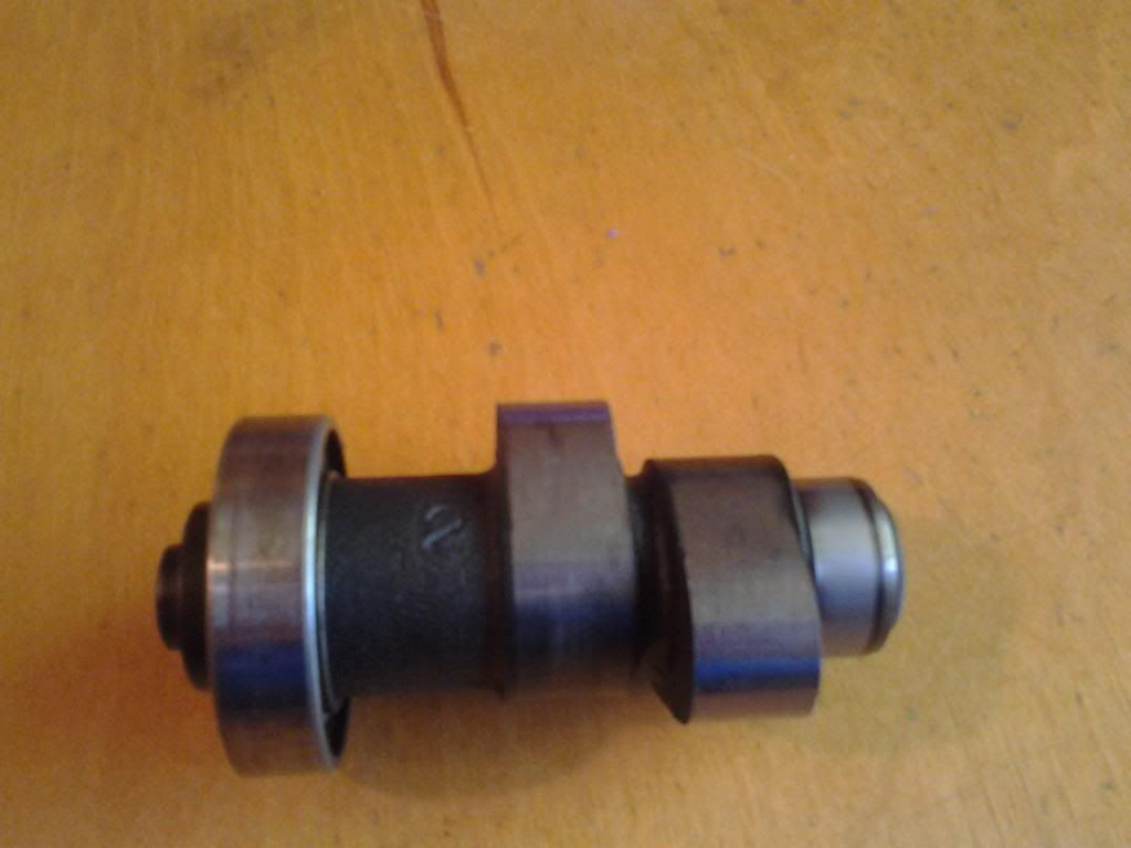
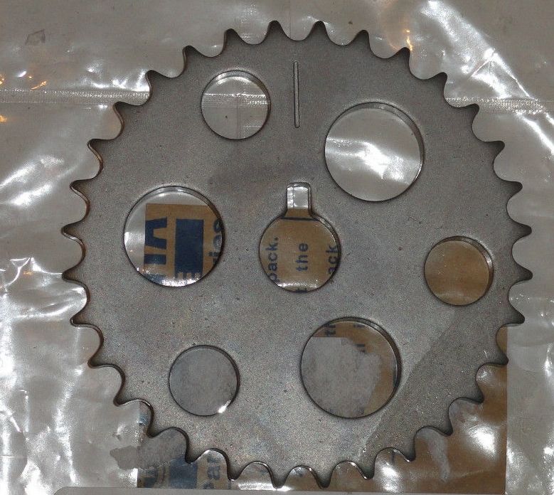
I would think a custom ground cam would have some type of trademark on it. The stock position for the cam gear says S I believe, and the locator pin hole is square NOT round.
 
me to i will take some pics and let your guys look and see what you think. then with the gear in S spot on the cam what do you use to line the gear up with the head? and i have been calling around getting prices on cams and it seems that no one does the billet cams anymore there all hard welded.
 
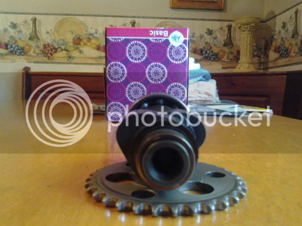
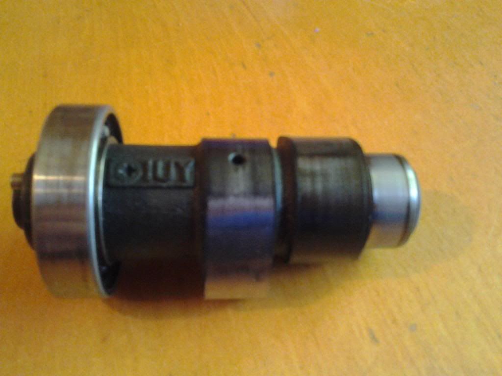
ok here are some pics
1024131008_zps5d147a55.jpg

1024131009_zpsce7bd60c.jpg

1024131010_zpsac9f22d1.jpg


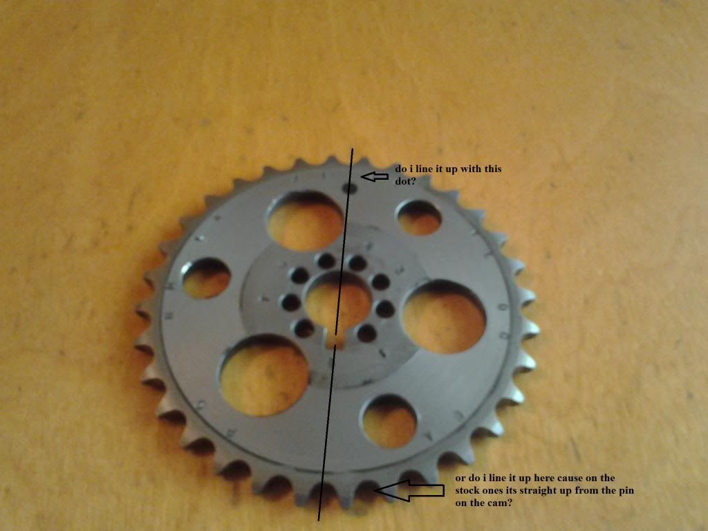
and then here is the gear, wondering where to line it up for stock.
camgear_zps894e0251.jpg

stockcamgear_zps5955585e.jpg
 
Can you get a closer/better picture of the side profile of the lobes. It looks like it may be hard welded. Normally you can see a difference in the metals.
 
ok thats what i was afraid of, so got to decide what to do with cam. thanks guys!
 
Does that gear say Megacycle? It doesn't look quite like mine. You need to line up the dowel pin in the cam with the timing mark on the head. Just like stock. Pretty easy...
 
no it dont say anything as far as brand. who else makes them? i wonder what that black dot is for, it maybe just paint that someone put on there.
 
yeah i dont i thought that it might what you line up to the head for timing. thanks for the help that could of not been good if i lined it up to that.
 
No prob. Always remember that the dowel pin in the cam always has to line up with the mark on the head.
 
ok that makes since, but man this is kind of confusing and cant find much info on them. does yours say mega on it? and in there catalog it has a pic and it looks just like mine even has the little black dot. And in the catalog it talks about using this hole for this much timing advance and gives you a letter to use for new timing mark, so that is confusing me, what you use that letter for if you still line the cam pin up. i will try to post pic of gear in catalog and the chart thing. just trying get it figured out before i get to that point so i will already know how it works.
 
Let me dig up the install instructions when I'm at work tomorrow. They are in my tool box. But, in a nutshell, you just turn the gear on the cam to the desired position (hole in cam), slip it on, and tighten down that bolt. Every letter changes the timing by 2.5* in one direction (advanced or retarded). Every number changes the timing by 2.5* (advanced or retarded). For example; the letters may be to retard the timing, so the power comes on harder near WOT. The numbers may be to advance the timing so the power comes on sooner off the bottom end.

Again, for example; letter A may retard the timing 2.5*, letter B 5*, letter C 7.5*, and so on.

Same is true for the numbers, but they do it in the opposite direction.

So, if you degreed your cam (with the gear in the stock position on the cam) and came up with say 3* advanced, and you wanted it as close to 0* possible, you would retard it 2.5*, giving you a total of .5* advanced cam timing.

This is all well fine and good, but, without a degree wheel for the crank and a method to measure valve lift, you are best to run the gear in the stock location (marked S).
 
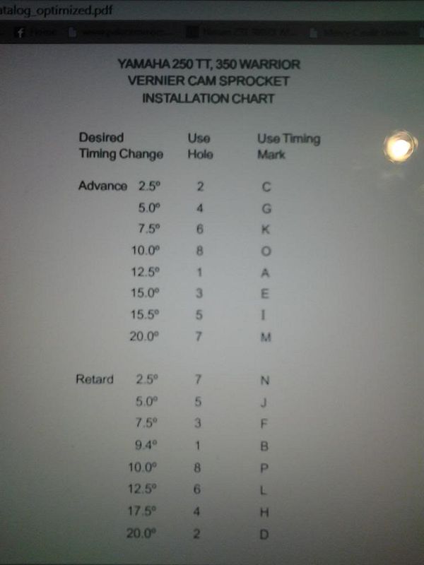
this is the chart so what do they mean when they say use timing mark....?
f709f170-174c-4076-991e-c7bcd0a590a9_zps2caa97bb.jpg


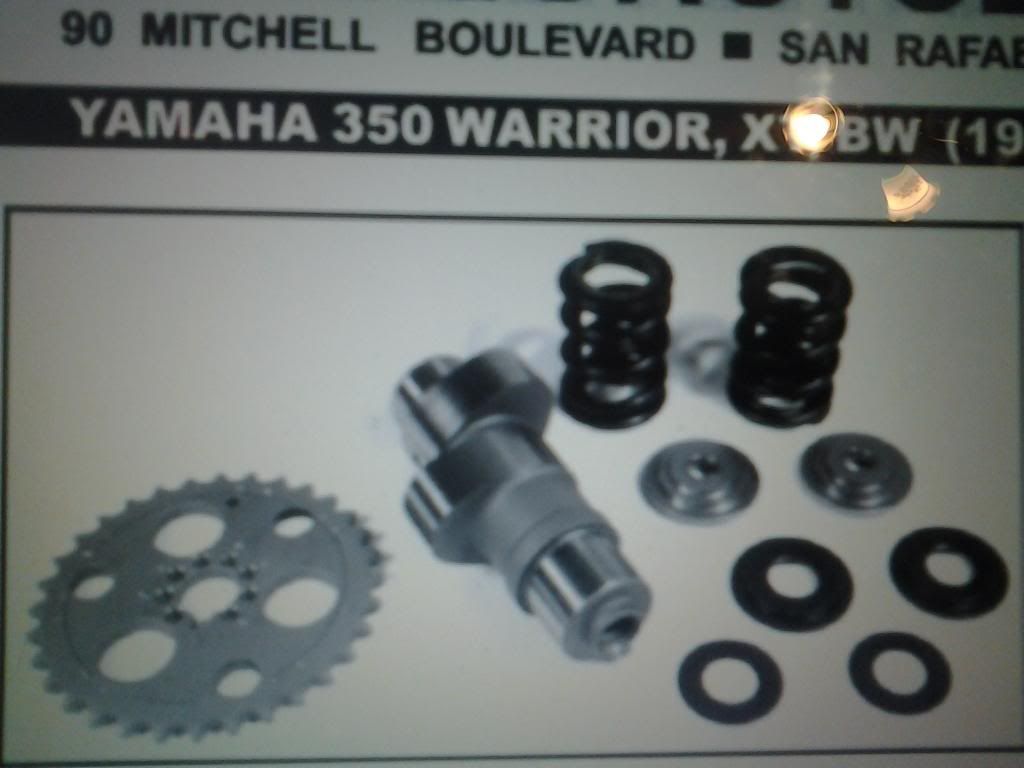
this is the gear in the catalog it has the black dot to.

1024132202_zpsd4460365.jpg
 
Last edited:
251-01 YAMAHA 500 TT/XT/SR VERNIER CAM SPROCKET 252-01 YAMAHA 250 TT, 350 WARRIOR CAM SPROCKET INSTRUCTIONS
The MEGACYCLE CAMS vernier drilled cam sprocket provides nine equally spaced drive pin holes to allow precise installation of the camshaft in a Yamaha 500 single engine. To utilize this sprocket, proceed as follows:
STEP 1: Install the cam using the stock pin hole, marked “S” and the stock timing marks. Measure the valve timing using whatever method you prefer. The method you use to “degree” the cam is not important, as long as you use it consistently.
STEP 2: After comparing the observed valve timing as measured in Step 1 with the desired valve timing, decide how much you would like to advance or retard the cam. It is possible that no change will be necessary. Remember that you can not alter the intake timing without a corresponding change in exhaust valve timing and vice versa.
STEP 3: Once you have decided how you would like to move the cam, use the attached chart to select the alternate sprocket drive pin hole and timing mark which will come closest to providing the desired change. The nine pin holes in conjunction with the thirty-four sprocket teeth will allow you to come within ± 1.2 crankshaft degrees of any desired location.
STEP 4: Install the cam using the new drive pin hole and timing mark. Recheck the valve timing. You should now have the desired timing. If, for some reason you wish to further alter the timing or the desired results were not achieved; repeat the procedure from Step 1.
It is very important that the surface where the sprocket rests on the end of the camshaft be very clean and free of any grit or foreign matter. The sprocket locating pin must be securely pressed into the cam and the bolt which tightens the sprocket onto the cam MUST be tightly in place. It may be necessary to use a small amount of “Loctite” to secure the bolt after you have decided which drive pin hole you will be using. The lip (or flange) which guides the bolt and holds the sprocket in place is delicate. Be careful not to chip or crack this lip. If damage does occur, the sprocket can easily become misaligned and cause problems.
Thank you for buying a MEGACYCLE product. If you need assistance, call between 9:00 PM and 5:00 PM Monday to Friday.
62
90 MITCHELL BOULEVARD „„ „„ „ SAN RAFAEL, CALIFORNIA 94903 „„ „„ „ 415 472-3195 „„ „„ „ FAX 415 472-1497 www.megacyclecams.com
Apr 10, 2012
YAMAHA 250 TT, 350 WARRIOR VERNIER CAM SPROCKET INSTALLATION CHART
Desired Use Use Timing Timing Change Hole Mark
Advance 2.5º 2 C 5.0º 4 G 7.5º 6 K 10.0º 8 O 12.5º 1 A 15.0º 3 E 15.5º 5 I 20.0º 7 M
Retard 2.5º 7 N 5.0º 5 J 7.5º 3 F 9.4º 1 B 10.0º 8 P 12.5º 6 L 17.5º 4 H 20.0º 2 D
 
Desired Use Hole Use Timing Mark
Timing Change

Advance2.5º 2 C 5.0º 4 G 7.5º 6 K
10.0º 8 O
12.5º 1 A
15.0 3 E
15.5º 5 I
20.0º 7 M


Retard 2.5º 7 N
5.0º 5 J
7.5º 3 F
9.4º 1 B
10.0º 8 P
12.5º 6 L
17.5º 4 H
20.0º 2 D
 
Back
Top